
Antenna Construction
To receive all the frequencies you hear through this website, I built two identical antennas from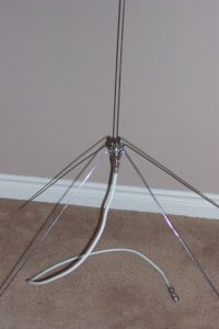 plans I found on the internet. Both antennas are mounted in the attic of my house, and are attached to a horizontal section of roofing support. The antennas are known as quarter wave antennas and are a simple design that can be constructed (or tuned) to receive whatever frequency range you are after.
There is a relationship between frequency and wavelength, so the physical size of the antenna is a function of the frequency range you are aiming for. To get the wavelength of any frequency there is a simple formula. 300 divided by the frequency in MHz.
A vertical length of wire or metal rod by itself will not perform that well. It needs the other half of the antenna known as ‘the ground plane’ to perform well. The easiest way to construct this is to add four similar lengths of wire. They are not electrically connected to the verticle length of wire, and we do need to bend them down at a 45 degree angle, so the impedance of the antenna ends up around 50 ohms, which is what the majority of communication devices perform best with, and is certainly what is required for radio scanners.
Construction of a quarter wave antenna is quite simple, and in the design that follows, the cost is very low. Some wire, coaxial cable and a couple of plugs. Any electronics or hobby store should have all the parts you need. In the Kitchener Waterloo area Orion Electronics is as good, and as reasonably priced as anyone.
Parts required for each antenna:
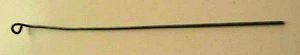
Solid wire – I use straightened out coat hangers for one antenna, and some similar thickness metal rods my wife said she bought at a hobby store for some reason. Any metal rod that holds it’s shape will suffice.
One SO239 plug
Coaxial cable
One PL259 plug
4 small bolts (small enough to fit in the holes of the SO239 plug on the corners) and matching nuts (depends on the construction method – see below)
Theory:
For the Waterloo Control Tower frequency of 126.0 MHz you apply the formula of 300 divided by 126.0, and come up with 2.38 meters. Since we are constructing a quarter wave antenna, we divide the calculated wavelength by 4. In this case 2.38 meters divided by 4. Therefore the length required for each metal radial on a quarter wave antenna tuned for 126.0 MHz is 2.38 divided by 4, which equals .60 meters, or 60 centimeters (23.6 inches)
Construction:
Before you cut your lengths for the four radials, you need to decide how you will fasten them to the SO239 socket. There are two ways to do this. One is to solder them directly to the corners of the socket (where the holes are), and the second is to use a small bolt to fasten Them to the socket. I used a combination of the two (bolts and solder). If you construct this antenna for a lower frequency, the radial will be longer of course, and the bolt method may help with portability, but either method works well.
Cut your lengths of wire. In this example they are each 60 cm long (after creating the loop at the end of four of them).
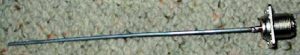
The verticle wire rod does not have a loop in it for either method as it gets soldered directly to the top of the SO239 plug.
Solder the length of wire without the loop into the socket on top of the SO239 plug. Metal coat hangers from the drycleaners are a good fit and allow a sufficient gap for solder to flow into the hole, creating a good electrical connection on the SO239 plug.
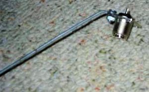
The other 4 lengths are bolted onto the socket using the holes on the corners, and then bent DOWN to an angle of 45 degrees (which gives you the 50 ohm match so that your radio is happy).
First of the radials bolted onto the socket.
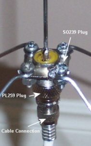
Your antenna is now completed, and you need to feed it and mount it. Attach your coaxial cable to the PL259 plug, and screw it into the SO239 platform and you have a new antenna to use.
A simple mounting method is a length of 25mm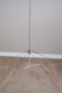 PVC pipe which allows the coax to be fed inside it, and also has the benefit of offering a snug fit for the PL259 plug, and holding the antenna up well. I simply attached the PVC pipe to a roof member with some copper plumbing U attachments.
A note about coaxial connecting cable. Both my antennas have about a 50 foot run of cable to the scanners. One antenna uses your basic cable TV 75 ohm cable, and the other antenna uses 50 ohm cabling. The reception with the 50 ohm cable may be slightly better, but in my particular setup you’d be hard pressed to really notice the difference. Now I am only a few kilometers from the airport and the police transmitters, and distance is a huge factor in determining the quality of reception. The farther away you are from the source transmitters, the more noticeable the effect will be between the 50 and 75 ohm cabling. The difference between the 50 and 75 ohm cabling will also become more noticeable the greater the distance between your antenna and the radio.
Because I’m using the antenna for reception only and not transmitting, the measurements are not as critical. I’m also using this antenna to pick up the Police and Fire transmission with excellent results. Their frequency range is in the 868 MHz area. Again, reception quality will vary depending on several factors, not limited to type of cabling, distance from transmitter source, antenna size, nearby sources of electrical interference , line of sight etc.
Many thanks to Matt of ScanACT in Australia for publishing this design originally.